Tempat: Kompleks Rakan Muda, Bukit Kiara
Masa: 2:00pm
Tarikh: 25.4.2009
Dijemput semua ahli ASTRA dan bukan ahli, rakan2 amatur dan komersial, penggemar radio komunikasi bersama menjayakan program di atas.
Pendaftaran keahlian juga disediakan..
Agenda:
1)Perasmian
2)Pembentangan Aktiviti Lepas
3)Mesyuarat - Minutes, Financial, Perlantikan Baru
4)Jamuan Ringan
Pertanyaan lanjut: 9w2mit - Maz
Sunday, April 19, 2009
Thursday, April 16, 2009
HOW HAM RADIO WORKS - PART 2 - 17/4/2009
Ham Radio Activities
Although a ham radio does broadcast in all directions, hams generally do not use their radios in a broadcast kind of way as a disk jockey would at a radio station. In normal AM or FM radio, one disk jockey transmits and thousands of people listen. Hams, on the other hand, conduct two-way conversations, often with another ham or with a group of hams in an informal roundtable. The roundtable of hams may be in the same town, county, state, country or continent or may consist of a mix of countries, depending on the frequency and the time of the day. Hams also participate in networks, often called nets, at predetermined times and frequencies to exchange third-party messages. In the case of disasters, hams exchange health and welfare information with other hams. Some hams use radioteletype, (RTTY) with computer screens replacing the noisy teletype machines of the past.
 Computer-assisted radioteletype |
Many hams get their start on VHF FM, using battery-operated hand-held transceivers set to transmit on one frequency and receive on another frequency. They use FM repeaters, set up and supported by local radio clubs. These repeaters borrow antenna space from TV-station-tower owners on top of mountains and high buildings to receive and re-broadcast signals to extend the range.
 When deadly floods struck central and southern Texas in mid-October 1998, amateur radio operators from four states volunteered their time. Susan Manor, NF0T, is shown helping with communications at the New Braunfels Red Cross office. |
The FM repeater receives one signal at a time and simultaneously rebroadcasts it on another frequency using many more watts of power than available from a small hand-held radio. This extends the range of the hand-held radio from a few miles to tens or hundreds of miles! The whole country has these repeaters! (Listen to one with a radio scanner to learn a lot about ham radio.) When a ham is traveling, he or she can find a repeater to use (great for tips on local restaurants), and carry on a nice, static-free, FM-radio-quality conversation via a radio that fits in the shirt pocket or purse. Linked repeaters allow fun wireless communications across an entire state with a hand-held radio.
Repeaters use common transmit and receive frequency pairs. The frequency pairs in use are informally assigned by groups of hams so that any frequency pair in use is far enough from another repeater so as not to cause unwanted interference.
Amateur radio satellites are a cutting-edge use of technology in amateur radio. Radio amateurs use their hand-held radios to communicate through an amateur radio satellite when the satellite is overhead. A current British satellite has a receiver (uplink) at 145.975 MHz and simultaneously rebroadcasts (downlink) at 435.070 MHz for one station at a time, as a repeater.
Natural disasters like hurricanes or tornadoes disrupt normal telephone and cell phone systems. Ham radio operators pitch in to help with emergency communications, and you will often hear about them on news reports.
On Space Shuttle missions, each member of the crew usually has an amateur radio operator's license. During breaks, astronauts hold their 1- to 5-watt VHF FM hand-held radios up to the shuttle window and chat with other hams for a few minutes, often at schools while the shuttle is in an orbit overhead! VHF transmissions have a limit to line-of-sight communications and normally do not travel over the horizon, so a conversation is limited to the time when the shuttle is overhead. The space station MIR used 145.985 MHz for similar conversations. Future ham radio efforts in space will focus on the use of amateur radio within the International Space Station (ARISS) project.
Ham Radio Equipment
A typical ham radio is a transmitter and a receiver, usually purchased as one unit, called a transceiver. Newer transceiver models often have semi-complicated controls and menu systems that may take some reading of the manual. You may be able to find an older transceiver with controls that are easier to use as a beginner, having the usual analog controls.
 Vintage tube-type short-wave receiver |
Hand-held transceivers have their own antennas. Many hams choose to do most of their operating from their automobile during commute times, using a magnetic mount antenna connected to an under-dash transceiver or a hand-held radio.
 Ham radio station in automobile |
Power Output
Depending on the size (hand-held or desktop), power can be from a few milliwatts to 1,500 watts. Many new hams are graduates from citizens band (CB) radio. Unlike the 5-watt limit on CB, hams can use quite a bit more power (1,500 watts).
The ham radio can fit in your shirt pocket, take up half of an attic or garage, sit on a desk next to the computer or go into a car. Right now, during the current sunspot cycle, it is possible to talk around the world during daylight hours running just a few watts of power. This particular type of radio-wave propagation is in the 28-MHz band (commonly called the 10-meter band) thanks to short-wave propagation (300 divided by the frequency in MHz is a quick way to convert to "meters").
Antennas
Little whip antennas, wire antennas in trees, and antennas atop a tower are all used, depending on the frequency in use. Lower frequencies have longer wavelengths. Longer wavelengths need larger antennas. The same antennas (used to transmit and receive) can be small, portable, put in trees or on the trunk of a car.
 Short-wave antenna |
The common 146-MHz (2-meter) antenna is a 19-inch quarter-wave whip. A wavelength at 146 MHz is approximately 2 (300 divided by 146) meters, and a quarter wave of 2 meters is about 19 inches (50 cm). Hams enjoy the fun of experimenting with various types of antennas. Some antennas are made of wire strung between trees. Be sure to use lightning protection for outside antennas!
Hams, including the writer of this article, have communicated with other hams using the following types of antennas with antenna tuners:
- Metal window screens in upper floors of hotels and motels
- Aluminum extension ladders, insulated from the ground, leaning against a house (the lower the frequency, the longer the ladder)
- Soldered-together rain gutters and downspouts
- Flat copper "burglar-tape" hidden behind wallpapered walls
- Extended "Slinky" toys supported by a rope through the middle, in an attic
- Camera-tripod-supported whip antenna
- Disguised flagpoles fed with buried coaxial cable
- Fine wires cast with a fishing rod between dormitory buildings
What keeps ham operators from transmitting on the same frequency?
Many hams can be on the same frequency, but it depends on the propagation factors. VHF and UHF are line-of-sight, so many hams can be on the same frequency in one state. On short-wave bands, radios have variable frequency tuning to allow moving your transmitted signal (in very small increments) in between two other transmitting stations. Hams often do a lot more listening than transmitting. Often, they listen for another ham that identifies the station as being in a sought-after county, state, or country.
 This LCD on a modern transceiver is displaying the spectrum of nearby stations. The band-scope at the bottom helps ham operators find signals. |
Hams collect confirmations of contacts using QSL cards. Hams collect the QSL cards and receive awards for contacting so many countries on certain frequency bands. VHF and UHF hand-held radios typically use channeled communications, using selectable fixed frequencies.
HOW HAM RADIO WORKS - PART 1 - 17/4/2009
How Ham Radio Works
by Brown, Gary. "How Ham Radio Works." 01 April 2000. HowStuffWorks.com.

Ham radio lets people talk across the globe, wirelessly and inexpensively. See more radio pictures.
A teen in Florida makes friends over the airwaves with a ham in Germany. An aircraft engineer in Washington participates in an annual contest and exchanges call signs with hams in 100 countries during a single weekend. In North Carolina, volunteers pass health and welfare messages in the aftermath of a hurricane.
This mix of fun, public service, friendship and convenience is the main feature of amateur radio. The true origin of the term "ham" seems to have been lost, but there are several theories. It may simply be a shortcut way of saying the first syllable of amateur radio, or it may have originally been used as an insult. Hams start out in amateur radio for many reasons, but they all have in common a basic knowledge of radio technology, regulations and operating principles.
Tune In |
Ham radio can be very portable and affordable. In this article, we will look at ham radio and show you how to get started in this wireless world!
Why would I get into ham radio?
Ham radio is for anyone who likes to communicate with others via wireless technology. It is also for anyone who enjoys experimentation. Licensed amateur radio operators communicate with each other in nearby places, across the country, around the world or even with astronauts in outer space!
Amateur radio is a worldwide group of people who communicate with each other over a wide frequency spectrum using many different types of wireless transmitting modes.
Often, younger hams get a chance to meet other hams of various ages and professions. For example, Kid's Day is an annual event that encourages young people to get on the air, perhaps with a family member or a neighbor who is a licensed amateur radio operator. The frequent networking often helps teens when they are making career or education choices and wish to get some advice (from professionals in many technical fields) that maybe mom, dad or the guidance counselor may not be able to give.
Today, there are more than 2.5 million around the world.
Frequencies and Transmitting Modes
Hams use a variety of frequencies for communications. Non-hams can "listen in" via their own receivers or radio scanners. Hams are able to use many frequency bands across the radio spectrum -- these frequencies are allocated by the FCC for amateur use. Hams may operate from just above the AM broadcast band to the microwave region, in the gigahertz range. Many ham bands are found in the frequency range that goes from above the AM radio band (1.6 MHz) to just above the citizens band (27 MHz). During daylight, 15 to 27 MHz is a good band for long-distance communications. At night, the band from 1.6 to 15 MHz is good for long-distance communications. These bands are often referred to historically as short-wave bands (as in "short-wave radio"). Unlike frequencies used by FM radio stations and TV stations, which are line-of-sight and therefore limited to 40 or 50 miles, short-waves "bounce" off the ionosphere from the transmitter to the receiver's antenna. The higher the frequency is, the "shorter" the wavelength is.
Some ham radio operators use the very reliable Morse code, while others use voice. Morse code signals (beeps) often get through when voice transmissions cannot. There are also very many digital modes as well, and hams use radio modems to communicate in various networks.
HOW RADIO WORK - Part 3 - 17/4/2009
The Simplest AM Receiver
In the case of a strong AM signal, it turns out that you can create a simple radio receiver with just two parts and some wire! The process is extremely simple -- here's what you need:- A diode - You can get a diode for about $1 at Radio Shack. Part number 276-1123 will do.
- Two pieces of wire - You'll need about 20 to 30 feet (15 to 20 meters) of wire. Radio Shack part number 278-1224 is great, but any wire will do.
- A small metal stake that you can drive into the ground (or, if the transmitter has a guard rail or metal fence nearby, you can use that)
- A crystal earphone - Unfortunately, Radio Shack does not sell one. However, Radio Shack does sell a Crystal Radio Kit (part number 28-178) that contains the earphone, diode, wire and a tuner (which means that you don't need to stand right next to the transmitter for this to work), all for $10.
You now need to find and be near an AM radio station's transmitting tower (within a mile/1.6 km or so) for this to work. Here's what you do:
- Drive the stake into the ground, or find a convenient metal fence post. Strip the insulation off the end of a 10-foot (3-meter) piece of wire and wrap it around the stake/post five or 10 times to get a good solid connection. This is the ground wire.
- Attach the diode to the other end of the ground wire.
- Take another piece of wire, 10 to 20 feet long (3 to 6 meters), and connect one end of it to the other end of the diode. This wire is your antenna. Lay it out on the ground, or hang it in a tree, but make sure the bare end does not touch the ground.
- Connect the two leads from the earplug to either end of the diode, like this:
 |
Now if you put the earplug in your ear, you will hear the radio station -- that is the simplest possible radio receiver! This super-simple project will not work if you are very far from the station, but it does demonstrate how simple a radio receiver can be.
Here's how it works. Your wire antenna is receiving all sorts of radio signals, but because you are so close to a particular transmitter it doesn't really matter. The nearby signal overwhelms everything else by a factor of millions. Because you are so close to the transmitter, the antenna is also receiving lots of energy -- enough to drive an earphone! Therefore, you don't need a tuner or batteries or anything else. The diode acts as a detector for the AM signal as described in the previous section. So you can hear the station despite the lack of a tuner and an amplifier!
The Crystal Radio Kit that Radio Shack sells (28-178) contains two extra parts: an inductor and a capacitor. These two parts create a tuner that gives the radio extra range. See How Oscillators Work for details.
Antenna Basics
You have probably noticed that almost every radio you see (like your cell phone, the radio in your car, etc.) has an antenna. Antennas come in all shapes and sizes, depending on the frequency the antenna is trying to receive. The antenna can be anything from a long, stiff wire (as in the AM/FM radio antennas on most cars) to something as bizarre as a satellite dish. Radio transmitters also use extremely tall antenna towers to transmit their signals.
The idea behind an antenna in a radio transmitter is to launch the radio waves into space. In a receiver, the idea is to pick up as much of the transmitter's power as possible and supply it to the tuner. For satellites that are millions of miles away, NASA uses huge dish antennas up to 200 feet (60 meters ) in diameter!
The size of an optimum radio antenna is related to the frequency of the signal that the antenna is trying to transmit or receive. The reason for this relationship has to do with the speed of light, and the distance electrons can travel as a result. The speed of light is 186,000 miles per second (300,000 kilometers per second). On the next page, we'll use this number to calculate a real-life antenna size.
Antenna: Real-life Examples
Let's say that you are trying to build a radio tower for radio station 680 AM. It is transmitting a sine wave with a frequency of 680,000 hertz. In one cycle of the sine wave, the transmitter is going to move electrons in the antenna in one direction, switch and pull them back, switch and push them out and switch and move them back again. In other words, the electrons will change direction four times during one cycle of the sine wave. If the transmitter is running at 680,000 hertz, that means that every cycle completes in (1/680,000) 0.00000147 seconds. One quarter of that is 0.0000003675 seconds. At the speed of light, electrons can travel 0.0684 miles (0.11 km) in 0.0000003675 seconds. That means the optimal antenna size for the transmitter at 680,000 hertz is about 361 feet (110 meters). So AM radio stations need very tall towers. For a cell phone working at 900,000,000 (900 MHz), on the other hand, the optimum antenna size is about 8.3 cm or 3 inches. This is why cell phones can have such short antennas.
 |  |  |  |
You might have noticed that the AM radio antenna in your car is not 300 feet long -- it is only a couple of feet long. If you made the antenna longer it would receive better, but AM stations are so strong in cities that it doesn't really matter if your antenna is the optimal length.
You might wonder why, when a radio transmitter transmits something, radio waves want to propagate through space away from the antenna at the speed of light. Why can radio waves travel millions of miles? Why doesn't the antenna just have a magnetic field around it, close to the antenna, as you see with a wire attached to a battery? One simple way to think about it is this: When current enters the antenna, it does create a magnetic field around the antenna. We have also seen that the magnetic field will create an electric field (voltage and current) in another wire placed close to the transmitter. It turns out that, in space, the magnetic field created by the antenna induces an electric field in space. This electric field in turn induces another magnetic field in space, which induces another electric field, which induces another magnetic field, and so on. These electric and magnetic fields (electromagnetic fields) induce each other in space at the speed of light, traveling outward away from the antenna.
For more information on radio and related topics, check out the links on the next page.
HOW RADIO WORK - Part 2 - 16/4/2009
A (Slightly) More Elaborate Radio
If you want to get a little more elaborate, use a metal file and two pieces of wire. Connect the handle of the file to one terminal of your 9-volt battery. Connect the other piece of wire to the other terminal, and run the free end of the wire up and down the file. If you do this in the dark, you will be able to see very small 9-volt sparks running along the file as the tip of the wire connects and disconnects with the file's ridges. Hold the file near an AM radio and you will hear a lot of static.
In the early days of radio, the transmitters were called spark coils, and they created a continuous stream of sparks at much higher voltages (e.g. 20,000 volts). The high voltage created big fat sparks like you see in a spark plug, and they could transmit farther. Today, a transmitter like that is illegal because it spams the entire radio spectrum, but in the early days it worked fine and was very common because there were not many people using radio waves.
Radio Basics: The Parts
As seen in the previous section, it is incredibly easy to transmit with static. All radios today, however, use continuous sine waves to transmit information (audio, video, data). The reason that we use continuous sine waves today is because there are so many different people and devices that want to use radio waves at the same time. If you had some way to see them, you would find that there are literally thousands of different radio waves (in the form of sine waves) around you right now -- TV broadcasts, AM and FM radio broadcasts, police and fire radios, satellite TVGPS signals, and so on. It is amazing how many uses there are for radio waves today (see How the Radio Spectrum Works to get an idea). Each different radio signal uses a different sine wave frequency, and that is how they are all separated. transmissions, cell phone conversations,
Any radio setup has two parts:
The transmitter
- The receiver
Radio Basics: Real-life Examples
A baby monitor is about as simple as radio technology gets. There is a transmitter that sits in the baby's room and a receiver that the parents use to listen to the baby. Here are some of the important characteristics of a typical baby monitor:- Modulation: Amplitude Modulation (AM)
- Frequency range: 49 MHz
- Number of frequencies: 1 or 2
- Transmitter power: 0.25 watts
 A typical baby monitor, with the receiver on the left and the transmitter on the right: The transmitter sits in the baby's room and is essentially a mini "radio station." The parents carry the receiver around the house to listen to the baby. Typical transmission distance is limited to about 200 feet (61 m). |
A cell phone is also a radio and is a much more sophisticated device (see How Cell Phones Work for details). A cell phone contains both a transmitter and a receiver, can use both of them simultaneously, can understand hundreds of different frequencies, and can automatically switch between frequencies. Here are some of the important characteristics of a typical analog cell phone:
- Modulation: Frequency Modulation (FM)
- Frequency range: 800 MHz
- Number of frequencies: 1,664 (832 per provider, two providers per area)
- Transmitter power: 3 watts

A typical cell phone contains both a transmitter and a receiver, and both operate simultaneously on different frequencies. A cell phone communicates with a cell phone tower and can transmit 2 or 3 miles (3-5 km).
Simple Transmitters
You can get an idea for how a radio transmitter works by starting with a battery and a piece of wire. In How Electromagnets Work, you can see that a battery sends electricity (a stream of electrons) through a wire if you connect the wire between the two terminals of the battery. The moving electrons create a magnetic field surrounding the wire, and that field is strong enough to affect a compass.
 |
Let's say that you take another wire and place it parallel to the battery's wire but several inches (5 cm) away from it. If you connect a very sensitive voltmeter to the wire, then the following will happen: Every time you connect or disconnect the first wire from the battery, you will sense a very small voltage and current in the second wire; any changing magnetic field can induce an electric field in a conductor -- this is the basic principle behind any electrical generator. So:
- The battery creates electron flow in the first wire.
- The moving electrons create a magnetic field around the wire.
- The magnetic field stretches out to the second wire.
- Electrons begin to flow in the second wire whenever the magnetic field in the first wire changes.
 |
One important thing to notice is that electrons flow in the second wire only when you connect or disconnect the battery. A magnetic field does not cause electrons to flow in a wire unless the magnetic field is changing. Connecting and disconnecting the battery changes the magnetic field (connecting the battery to the wire creates the magnetic field, while disconnecting collapses the field), so electrons flow in the second wire at those two moments.
Simple Transmitters: Make Your Own
To create a simple radio transmitter, what you want to do is create a rapidly changing electric current in a wire. You can do that by rapidly connecting and disconnecting a battery, like this:
 When you connect the battery, the voltage in the wire is 1.5 volts, and when you disconnect it, the voltage is zero volts. By connecting and disconnecting a battery quickly, you create a square wave that fluctuates between 0 and 1.5 volts. |
A better way is to create a continuously varying electric current in a wire. The simplest (and smoothest) form of a continuously varying wave is a sine wave like the one shown below:
 A sine wave fluctuates smoothly between, for example, 10 volts and -10 volts. |
By creating a sine wave and running it through a wire, you create a simple radio transmitter. It is extremely easy to create a sine wave with just a few electronic components -- a capacitor and an inductor can create the sine wave, and a couple of transistors can amplify the wave into a powerful signal (see How Oscillators Work for details, and here is a simple transmitter schematic). By sending that signal to an antenna, you can transmit the sine wave into space.
Transmitting Information
If you have a sine wave and a transmitter that is transmitting the sine wave into space with an antenna, you have a radio station. The only problem is that the sine wave doesn't contain any information. You need to modulate the wave in some way to encode information on it. There are three common ways to modulate a sine wave:- Pulse Modulation - In PM, you simply turn the sine wave on and off. This is an easy way to send Morse code. PM is not that common, but one good example of it is the radio system that sends signals to radio-controlled clocks in the United States. One PM transmitter is able to cover the entire United States!
 |
- Amplitude Modulation - Both AM radio stations and the picture part of a TV signal use amplitude modulation to encode information. In amplitude modulation, the amplitude of the sine wave (its peak-to-peak voltage) changes. So, for example, the sine wave produced by a person's voice is overlaid onto the transmitter's sine wave to vary its amplitude.
 |
- Frequency Modulation - FM radio stations and hundreds of other wireless technologies (including the sound portion of a TV signal, cordless phones, cell phones, etc.) use frequency modulation. The advantage to FM is that it is largely immune to static. In FM, the transmitter's sine wave frequency changes very slightly based on the information signal.
 |
Once you modulate a sine wave with information, you can transmit the information!
Receiving an AM Signal
Here's a real world example. When you tune your car's AM radio to a station -- for example, 680 on the AM dial -- the transmitter's sine wave is transmitting at 680,000 hertz (the sine wave repeats 680,000 times per second). The DJ's voice is modulated onto that carrier wave by varying the amplitude of the transmitter's sine wave. An amplifier amplifies the signal to something like 50,000 watts for a large AM station. Then the antenna sends the radio waves out into space.
So how does your car's AM radio -- a receiver -- receive the 680,000-hertz signal that the transmitter sent and extract the information (the DJ's voice) from it? Here are the steps:
 |
- Unless you are sitting right beside the transmitter, your radio receiver needs an antenna to help it pick the transmitter's radio waves out of the air. An AM antenna is simply a wire or a metal stick that increases the amount of metal the transmitter's waves can interact with.
- Your radio receiver needs a tuner. The antenna will receive thousands of sine waves. The job of a tuner is to separate one sine wave from the thousands of radio signals that the antenna receives. In this case, the tuner is tuned to receive the 680,000-hertz signal.
Tuners work using a principle called resonance. That is, tuners resonate at, and amplify, one particular frequency and ignore all the other frequencies in the air. It is easy to create a resonator with a capacitor and an inductor (check out How Oscillators Work to see how inductors and capacitors work together to create a tuner).
- The tuner causes the radio to receive just one sine wave frequency (in this case, 680,000 hertz). Now the radio has to extract the DJ's voice out of that sine wave. This is done with a part of the radio called a detector or demodulator. In the case of an AM radio, the detector is made with an electronic component called a diode. A diode allows current to flow through in one direction but not the other, so it clips off one side of the wave, like this:
 |
- The radio next amplifies the clipped signal and sends it to the speakers (or a headphone). The amplifier is made of one or more transistors (more transistors means more amplification and therefore more power to the speakers).
In an FM radio, the detector is different, but everything else is the same. In FM, the detector turns the changes in frequency into sound, but the antenna, tuner and amplifier are largely the same.
HOW RADIO WORK - Part 1 - 15/4/2009
How Radio Works
by Brain, Marshall. "How Radio Works." 07 December 2000. HowStuffWorks.com.
Inside this Article
Radio waves control everything from wireless networks to garage door openers. See radio pictures.
"Radio waves" transmit music, conversations, pictures and data invisibly through the air, often over millions of miles -- it happens every day in thousands of different ways! Even though radio waves are invisible and completely undetectable to humans, they have totally changed society. Whether we are talking about a cell phone, a baby monitor, a cordless phone or any one of the thousands of other wireless technologies, all of them use radio waves to communicate.
Here are just a few of the everyday technologies that depend on radio waves:
- AM and FM radio broadcasts
- Cordless phones
- Garage door openers
- Wireless networks
- Radio-controlled toys
- Television broadcasts
- Cell phones
- GPS receivers
- Ham radios
- Satellite communications
- Police radios
- Wireless clocks
The list goes on and on... Even things like radar and microwave ovens depend on radio waves. Things like communication and navigation satellites would be impossible without radio waves, as would modern aviation -- an airplane depends on a dozen different radio systems. The current trend toward wireless Internet access uses radio as well, and that means a lot more convenience in the future!
Tune In |
The funny thing is that, at its core, radio is an incredibly simple technology. With just a couple of electronic components that cost at most a dollar or two, you can build simple radio transmitters and receivers. The story of how something so simple has become a bedrock technology of the modern world is fascinating!
In this article, we will explore the technology of radio so that you can completely understand how invisible radio waves make so many things possible!
The Simplest Radio
Radio can be incredibly simple, and around the turn of the century this simplicity made early experimentation possible for just about anyone. How simple can it get? Here's an example:
- Take a fresh 9-volt battery and a coin.
- Find an AM radio and tune it to an area of the dial where you hear static.
- Now hold the battery near the antenna and quickly tap the two terminals of the battery with the coin (so that you connect them together for an instant).
- You will hear a crackle in the radio that is caused by the connection and disconnection of the coin.
 By tapping the terminals of a 9-volt battery with a coin, you can create radio waves that an AM radio can receive! |
Your battery/coin combination is a radio transmitter! It's not transmitting anything useful (just static), and it will not transmit very far (just a few inches, because it's not optimized for distance). But if you use the static to tap out Morse code, you can actually communicate over several inches with this crude device!
Sunday, April 12, 2009
Nokia Symbians Secret Codes
Nokia Symbians Secret Codes
Nokia Code function
*3370# This Nokia code activates Enhanced Full Rate Codec (EFR) - Your Nokia cell phone uses the best sound quality but talk time is reduced my approx. 5%
#3370# Deactivate Enhanced Full Rate Codec (EFR)
*#4720# Activate Half Rate Codec - Your phone uses a lower quality sound but you should gain approx 30% more Talk Time
*#4720# With this Nokia code you can deactivate the Half Rate Codec
*#0000# Displays your phones software version, 1st Line : Software Version, 2nd Line : Software Release Date, 3rd Line : Compression Type
*#9999# Phones software version if *#0000# does not work
*#06# For checking the International Mobile Equipment Identity (IMEI Number)
#pw+1234567890+1# Provider Lock Status. (use the "*" button to obtain the "p,w" and "+" symbols)
#pw+1234567890+2# Network Lock Status. (use the "*" button to obtain the "p,w" and "+" symbols)
#pw+1234567890+3# Country Lock Status. (use the "*" button to obtain the "p,w" and "+" symbols)
#pw+1234567890+4# SIM Card Lock Status. (use the "*" button to obtain the "p,w" and "+" symbols)
*#147# This lets you know who called you last (Only vodofone)
*#1471# Last call (Only vodofone)
*#21# This phone code allows you to check the number that "All Calls" are diverted to
*#2640# Displays phone security code in use
*#30# Lets you see the private number
*#43# Allows you to check the "Call Waiting" status of your cell phone.
*#61# Allows you to check the number that "On No Reply" calls are diverted to
*#62# Allows you to check the number that "Divert If Unreachable (no service)" calls are diverted to
*#67# Allows you to check the number that "On Busy Calls" are diverted to
*#67705646# Phone code that removes operator logo on 3310 & 3330
*#73# Reset phone timers and game scores
*#746025625# Displays the SIM Clock status, if your phone supports this power saving feature "SIM Clock Stop Allowed", it means you will get the best standby time possible
*#7760# Manufactures code
*#7780# Restore factory settings
*#8110# Software version for the nokia 8110
*#92702689# Displays - 1.Serial Number, 2.Date Made, 3.Purchase Date, 4.Date of last repair (0000 for no repairs), 5.Transfer User Data. To exit this mode you need to switch your phone off then on again
*#94870345123456789# Deactivate the PWM-Mem
**21*number# Turn on "All Calls" diverting to the phone number entered
**61*number# Turn on "No Reply" diverting to the phone number entered
**67*number# Turn on "On Busy" diverting to the phone number entered
12345 This is the default security code
press and hold # Lets you switch between lines
The Operating Systems
Symb OS v6.1
Symb OS v7.0
Symb OS v8.0
Symb OS v8.1
Symb OS v9.1
Symb OS v6.1
- Nokia 7650
Nokia 3650
Nokia 3660
Nokia N-Gage
Nokia N-Gage QD
Siemens SX-1
Sendo X
Symb OS v7.0
- Nokia 3230
Nokia 6600
Nokia 6620
Nokia 6260
Nokia 6670
Nokia 7610
Panasonic X700
Panasonic X800
Symb OS v8.0
- Nokia 6630
Nokia 6680
Nokia 6681
Symb OS v8.1
- Nokia N70
Nokia N90
Symb OS v9.1
- Nokia N91
Nokia 3250
Nokia E60
Nokia E61
Nokia E70
Nokia N71
Nokia N80
Nokia N92
Nokia phones service codes
*#0000# - SW version
*#06# - IMEI
*#war0anty# - SIMLOCK info
*3370# - Enhanced Full Rate ON
#3370# - OFF
*4720# - alternative sound quality codec ON
#4720# - OFF
*#7780# - default factory settings
*#7760# - production serial no.
*#2820# - Bluetooth info.
*#73# - reset phone timers and game scores.
*#7370925538# - delete all the content of the wallet and the wallet code.
*#7370# - soft format — erases all telephone memory.
[Green]*3 - hard format — if only the telephone memory is formatted, puts back the attitudes and reboots
*#delset# - MMS/GPRS settings removal
NOTE: code depends on phone model
Friday, April 10, 2009

Walk up to any ham who has already put a repeater on the air and ask him, "What's the toughest technical problem you had with it?" He will probably say that obtaining sufficient signal isolation between the transmitter and receiver was the toughest. Satisfactory isolation can be gotten, but always for a price. Many of the solutions to this problem compromise receiver sensitivity or transmitter power output. Other solutions throw off the balance between receiver and transmitter coverage areas. When a duplexer is used, insertion loss is the compromise. But any insertion loss is more than offset by the use of one antenna for both the transmitter and receiver. Using one antenna assures equal antenna patterns for both transmitting and receiving. Duplexers have been in use by many commercially operated repeaters for many years. A large number of these systems use frequency separation of two percent or more between input and output channels. Amateur 2-meter repeaters have a separation of only 0.4 percent, or 600 khz. A decrease in frequency separation makes the job of providing good isolation even more difficult. A duplexer must meet some basic requirements. It must attenuate the transmitter carrier, this prevents receiver overloading, which in turn would reduce receiver sensitivity. A duplexer must also attenuate any noise or spurious energy from the transmitter on or near the receive frequency. In addition, a duplexer must provide a proper match between transmitter, antenna and receiver. If you are having trouble visualizing these functions, Fig. 13 will help. Transmitter output on 146.94 MHz going from point C to D should not be attenuated. However, the transmitter energy should be greatly attenuated between points B and A. Duplexer section 2 should attenuate any noise or signals that are on or near the receiver input frequency of 146.34 MHz. For good reception, the noise and spurious signal level must be less than -130 dB (0 dBm = 1 milliwatt into 50 ohms). Typical transmitter noise 600 kHz from the carrier frequency is 80 dB below the transmitter power output. For 60 watts of output (+48 dBm), the noise is -32 dBm. The duplexer must make up the difference between - 32 and -130 dBm, or -98 dBm. Now, let's talk about the received signal. First of all, the received signal must go from point B to A with a minimum of attenuation. Section 1 of the duplexer needs to provide enough attenuation of transmitted energy to prevent receiver overload. For an average receiver, the transmitter signal must be less than -30 dBm to meet this requirement. It is the job of duplexer section 1 to make up the difference between the transmitter output of + 48 dBm and the receiver overload point of -30 dBm. One thing that many duplexers have in common is the use of high-Q coaxial cavities. The loaded Q of a cavity is affected by electrical conductivity and dielectric losses. Surface loss can be reduced by silver plating, although clean copper is adequate. Air dielectric duplexers cavities are the most practical for amateur duplexers.
The Circuit
A quarter wavelength resonator was selected for this duplexer design. The length of the center conductor is adjusted by turning a threaded rod, which tunes the cavity to frequency. Energy is coupled into and out of the tuned circuit by the coupling loops extending through the top plate. The cavity functions as a series resonant circuit. When a capacitor or inductor is connected across a series resonant circuit, an anti resonant notch is produced, and the resonant frequency is shifted. If a capacitor is added, the notch appears below the resonant frequency. Adding an inductance will make the notch appear above the resonant frequency, and the value of either component will determine the spacing between the notch and the resonant frequency. Fig. 14 shows the band-pass characteristics of the cavity with shunt elements. With the cavity tuned to 146.94 MHz, and a shunt capacitor connected from input to output, a 146.34 MHz signal is attenuated 35 dB. With a cavity having an inductance across it, and tuned to 146.34 MHz, the attenuation at 146.94 MHz is 35 dB. Insertion loss in both cases is 0.4 dB. Three cavities with a shunt capacitor are tuned to 146.94 MHz and connected together with short lengths of coaxial cable. The attenuation at 146.34 MHz is more than 100 dB, while insertion loss is 1.5 dB. Response curves for a six cavity duplexer are given in Fig. 15. The schematic diagram for the complete duplexer is shown in Fig. 16.
Construction
A small lathe for metal work will machine the brass top plate, the threaded tuning plunger bushing and the Teflon insulator bushing. Fig. 17 shows the completed top plate assemblies, one with a capacitor, one with inductor. The dimensions of these parts are given in Fig. 18. All the other parts can be made with hand tools. "DWV" copper pipe is used for the outer conductor of the cavities. See Fig. 20 for a complete overview of an individual cavity. The wall thickness is 0.058 inch (1.5 mm), with an outside diameter of 4-1/8 inches (105 mm). When you buy the pipe, borrow a tubing cutter large enough to handle this size. The wheel of the cutter should be tight and sharp. Make slow, careful cuts so the ends will be square. The outer conductor is 22-1/2 inches (571 mm) long. The inner conductor is made from type "M" copper tubing having an outside diameter of 1-3/8 inches (35 mm). A six inch length of one inch OD brass tubing is used to make the tuning plunger. Soft solder is used throughout the assembly. Unless you have had experience with silver solder, do not use it. Eutectic type 157 solder with paste or acid flux makes very good joints. This type has a slightly higher melting temperature than ordinary lead Tin alloy and has considerably greater strength. First solder the inner conductor to the top plate. Then finger stock can be soldered inside the lower end of the inner conductor, temporarily held in place with a plug made of aluminum or stainless steel. While soldering, do not allow the flame from the torch to overheat the finger stock. The plunger bushing is soldered into the tuning plunger and a 20 inch length of threaded rod is soldered into the bushing. Cut six slots in the top of the outer conductor. They should be 5/8 inch (16 mm) deep and equally spaced around the tubing. The bottom end of the 4 inch tubing is soldered to the square bottom plate. Because the center conductor has no support at one end, the cavities must be mounted vertically. The size and position of the tuning loops are critical. Follow the given dimensions closely. Both loops should be 1/8 inch (3.2 mm) away from the center conductor on opposite sides. Connect a solder lug to the ground end of the loop. Then fasten the lug to the top plate with a screw. The free end of the loop is insulated by Teflon bushings where it passes through the top plate to connect to the BNC fittings. Before final assembly of the parts, clean them thoroughly. Soap filled steel wool pads and hot water work fine. See that the finger stock makes a firm contact with the tuning plunger. The top plate should fit snugly in the top of the outer conductor. A large hose clamp tightened around the outer conductor will keep the top plate in place.
Tuning
Wait until the cavities have been checked for band-pass characteristics and insertion loss before installing the anti resonant elements, C1 and L1. See Fig. 14. It is preferable to use laboratory test equipment when tuning the duplexer. A second method uses a low power transmitter with an rf detector and a VTVM. Both methods are shown in Fig. 19. With the test equipment connected as shown in Fig. 19A, adjust the signal generator frequency to the desired repeater input frequency. Connect a calibrated step attenuator between points X and Y. With no attenuation, adjust the HP-415 for 0 on the 20 dB scale. You can check the calibration of the 415 by switching in different amounts of attenuation and noting the meter reading. You might note a small error at either high or very low signal levels. Next, remove the step attenuator and replace it with a cavity that has the shunt inductor, L1, in place. Adjust the tuning screw for maximum reading on the 415 meter. Remove the cavity and connect point X to Y. Set the signal generator to the repeater output frequency and adjust the 415 for a 0 reading on the 20 dB scale. Reinsert the cavity between X and Y and adjust the cavity tuning for minimum reading on the 415. The notch should be sharp and have a minimum depth of -35 dB. It is important to maintain this minimum reading on the meter while tightening the lock nut on the tuning shaft. To check the insertion loss of the cavity, the output from the signal generator should be reduced, and the calibration of the 415 meter checked on the 50 dB expanded scale. Use a fixed 1 dB attenuator to make certain the error is less than 0.1 dB. Replace the attenuator with the cavity and read the loss. The insertion loss should be 0.5 dB or less. The procedure is the same for tuning all six cavities, except that the frequencies are reversed for those that have the shunt capacitor installed.
Adjustment with Minimum Equipment
Try getting a tube transmitter when using this method of adjustment. You will want a minimum of spurious signals, otherwise, there will be a lot of false indications. The VTVM should be capable of reading 0.5 volt or less, full scale. The rf probe should be good to 100 MHz or higher. Sections of RG-58/U coaxial cable are used as attenuators. See Fig. 19B. The loss in these 140 foot sections is nearly 10 dB and will help isolate the transmitter in case of mismatch during tuning. Set the transmitter on the repeater input frequency and connect P and Q. Obtain a reading between 1 and 3 volts on the VTVM. Insert a cavity with shunt capacitors in place between P and Q and adjust the cavity tuning for minimum reading on the VTVM. It should read between 0.01 and 0.05 volt. You can calculate the rejection in dB by the formula 20 log V1/V2. It should be -35 dB, minimum. Check insertion loss by putting the transmitter on the repeater output frequency and noting the VTVM reading with the cavity in and out of the circuit. You can make a 0.5 dB attenuator from seven feet (2.13 m) of RG-58/U. This seven foot section can be used to check the calibration of the detector probe and the VTVM. Cavities using a shunt inductance can be tuned the same way but with the frequencies reversed. If you try to tune two or more cavities connected together, transmitter noise can cause the rejection readings to be low. In other words, there will be less attenuation.
Results
The duplexer is conservatively rated at 150 watts input, but it should withstand up to 300 watts. Silver plating the interior of the cavities is a good idea if the input power will exceed 150 watts. A duplexer using plated cavities has an insertion loss of under 1 dB, and a rejection of more than - 100 dB. Unplated cavities should be taken apart every two years, cleaned thoroughly, and retuned.
Miscellaneous Notes
1) Double shielded cable is a must throughout the system.
2) The VSWR from the antenna should not exceed 1.2:1 for proper duplexer performance.
3) Good shielding of the transmitter and receiver at the repeater is essential.
4) The antenna should have four or more wavelengths of vertical separation from the repeater.
5) Conductors in the near field of the antenna should be well bonded and grounded to eliminate noise.
6) The feed line should be well bonded and secured to the tower or mast.
7) Feed lines from other antenna in the near field of the repeater antennas should be well bonded and as far from the repeater antenna as possible.
8) Individual cavities or pairs can be used to improve the performance of split antenna or split site repeaters.
9) Individual cavities can be used to help solve intermodulation problems.
This article is part of the "Repeater Builder's Technical Information Page."
Original article appeared QST magazine as described by W1GAN July 1972.
The article also appeared in the ARRL Antenna Book, and FM & Repeaters Manual.
Copyright ARRL, All Rights Reserved.
HTML Copyright 1999 W3KKC, All Rights Reserved.
Thursday, April 9, 2009
June QST: Lab Notes - June 1996 - Page 1
ARRL 1996 QST/QEX/NCJ CD C i ht (C) 1997 b Th A i R di R l L I
Lab Notes, Prepared by the ARRL Laboratory Staff
Troubleshooting Electrical Noise
Many devices can generate electrical noise. Much of this noise relates to the distribution of the ac power we take for granted in our homes. This month, ARRL Laboratory Supervisor Ed Hare, KA1CV, offers some pointers about locating power-line noise.
Q: I would like to listen to weak signals on my HF station, but there is an S9 noise on almost all frequencies. The noise is pretty badon 160 meters, but I can sometimes hear it on 10 meters, too. The sound is a raucous buzz that varies in intensity. Sometimes it has a higher, varying pitch that sounds much like my electric drill. How can I find the source of this noise?
A: That sounds like two sources. They are probably devices that are connected to the ac-power lines. Each could be anything from ahome electric appliance to power-line equipment or hardware.
Q: That covers a lot of territory. Can you narrow the search a little?
A: It’s difficult to name a source from the sound alone, but there are some easy diagnostic rules you can apply. Buzzing sounds usually result from an electrical arc or spark. An arc intensifies at the positive and negative voltage peaks of the 60-Hz ac voltage waveform, at a 120-Hz frequency. Higher, variable-pitch sounds often come from variable-speed electric motors. The pitch varies with motor speed. If the noise strength varies with the weather, the source is usually outdoors, exposed to the elements to one degree or another. So, if the problem goes away (or gets worse) during wet weather, think of the power lines first. If the noise varies with the time of day, it usually relates to activities of people. Note the sound pattern of a noise. Drills, sewing machines, kitchen mixers, heating pads and other devices have characteristic operating patterns that you can hear. Think of home appliances, fluorescent light fixtures, neon signs or factory equipment that operates when a business opens, etc. These are not iron-clad rules, but they form a good starting point. In some cases, electrical noise indicates a dangerous condition that needs correction, such as an arc inside a home appliance.
Q: I should find it! Where do I begin?
A The source is most likely close to you; so let’s begin at home. First, let’s check your radio—just to be sure. Disconnect the antenna. If possible, use a battery to power the radio or test the radio at a distant location. If the noise goes away, the radio is fine. For portable radios without removable antennas, move the radio (at least a block, perhaps a mile). If the noise strength varies with location, the radio is okay.
Q: Whew! The noise went away; I was worried that my radio was broken. What should I do next?
A: Let’s check your house. First, find a battery-operated AM-broadcast receiver. Tune the radio to a clear frequency and make sure that you can hear the noise on the radio. If so, go to your breaker panel or fuse box. (If you don’t normally reset breakers or replace fuses, get a qualified person to help.) Listen to the radio as you switch each of the circuits off and then on. If the noise suddenly disappears as you switch a circuit off, the source is something on that circuit. Next, unplug devices on that circuit, one at a time. When the noise comes and goes with your action, you have located the noise source. The device may not be malfunctioning, but have it checked out by a qualified service person to be sure.
Q: I found an old electric clock that seems to make noise sporadically. Is it worth fixing?
A: Probably not. The noise indicates an intermittent electrical connection inside the clock, which may be unsafe. Only qualified service personnel should repair consumer equipment. For example, installing capacitors unsuited for use on ac lines could create a fire hazard. Professional repair would cost more than an inexpensive clock is worth—unless it has great sentimental value.
Q: That eliminated the worst noise, but I still hear a number of other noises from time to time. Where else can I look?
A: You may have two or more noisy devices in your house. You may also hear noise sources at your neighbors’ houses. Pay attention to activity in your neighborhood. For example, does the noise appear when your neighbors are outside, perhaps using their electric bug “zapper”? Maybe you hear noise when another neighbor uses an old fluorescent light in the basement. If you see no suspects, try some direction finding (DFing) and investigation.
Q: I don’t know anything about DFing; don’t I need special equipment?
A: DFing is a specialty, but its application to electrical noise is fairly simple. You can begin DFing by walking around with a portable AM/SW/VHF AM receiver! (You need an AM receiver because most FM receivers reject electrical noise.) Fortunately, most portable VHF scanners and some ham H-Ts tune the aircraft bands, which use AM instead of FM. You will need to do a bit of walking or driving. Some electrical noise can propagate for miles! When the power lines radiate noise, standing waves can form on the power-line “antenna.” The resulting amplitude peaks and valleys may occur far from the source. Fortunately, most electrical noise is broadband and usually stronger at lower frequencies. Although you may hear noise on an AM-broadcast receiver miles from the source, you usually won’t hear it on VHF until the source is nearby. You can use this to advantage. See Figure 1 (attached). You can use the AM broadcast band, or 160 or 80 meters, to locate the neighborhood of the noise. Because you can hear some of the noises on 10 meters, those sources must be nearby. Once you have located the general area, tune the radio higher in frequency. Find a frequency where the signal is weak, and start moving around. As long as the signal becomes stronger, you are approaching the source. Keep tuning to higher frequencies. When you can hear the signal on VHF, you are quite close to the source. To continue, use a directional antenna, or get the receiver very close to each house in the area. (An article describing a directional antenna and aircraft-band receiver appeared in September 1992 QST.) [1] You can pinpoint a house with a VHF receiver by collapsing the receiver’s whip antenna to a few inches and placing it near the power meter of each house—with the permission of the occupant, of course. (This may be marginally effective in apartment buildings, too, but not as reliable.) If you do locate a specific house, you will need to repeat the troubleshooting steps from your own home. Figure 1—The amplitude of electrical noise varies as a function of frequency.
Q: I found two sources—an aquarium heater and a food blender—in neighboring houses. The first neighbor is willing to buy a new heater. What kind should he buy?
A: There are no lists of quiet appliances. Take your portable receiver to the pet store and listen to several operating heaters to determine which is least noisy. Most new appliances radiate less noise than those made many years ago.
Q: Thanks. What can I do about the food blender? The service shop people say it works fine.
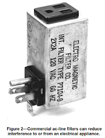
A: An external ac-line filter may reduce the noise. The filter plugs into an ac outlet, and the appliance plugs into the filter. The blender will still be noisy, but your location should be much quieter because the filter keeps the noise from being conducted onto the power-line, which can act as an antenna, radiating the noise. An ac-line filter can also help prevent ac noise from entering an appliance via the ac line. It may make a stereo, or station receiver, perform better if noise is being conducted on the ac line. Note that a surge filter is probably not an ac-line filter. Ac-line filters are often available at electrical supply houses and other retail outlets. Industrial Communications Engineers (ICE) is one manufacturer of commercial ac-line filters. [2] Figure 2 shows an ac line filter.
Figure 2—Commercial ac-line filters can reduce interference to or from an electrical appliance.
Q: That’s better! I hear no noise on 40 meters and higher frequencies, but 80 meters still has a moderately strong, steady buzzing that goes away on rainy days. Is that a bad power line? Should I contact the power company?
A: The noise is affected by weather, so it’s outdoors and probably something connected to the power lines. (If the noise only appeared at night, I would suspect a street lamp. Their starting circuits can become noisy as they cycle on and off trying to start a bad lamp. Many street lamps use gas-discharge bulbs, which can cause noise.) Although most high utility power distribution systems generate some noise, FCC regulations prohibit them from interfering with communications. If power-company equipment is the noise source, the utility company must correct it. (They are not responsible for interference caused by their customers, however.) In theory, you could report the problem to the utility company and expect them to correct it. In practice, however, the experience with each utility varies quite a bit. Even those with the necessary personnel and equipment to diagnose the problem may have a long waiting list for corrections. In most cases, it’s best for you to locate the problem for them. A combination of the techniques we’ve discussed can often identify a specific pole. First, track the problem to a neighborhood using the AM-broadcast band, then switch to VHF to get close. Once you are close, you may be able to hear or see the arc! A careful inspection with a set of binoculars may prove productive.
Q: I’ve narrowed the search to a city block. What can I do from here?
A: Call the utility repair people and leave the solution to them. In many cases, defective or cracked pole hardware causes electrical noise. Hardware and live lines occasionally fall from poles during repairs or when someone strikes a pole. Leave this danger to those trained to deal with it! The utility companies usually have sophisticated equipment and a trained RFI investigator who identifies the problem pole. With that done, the repair office dispatches a crew to make the repairs.
Q: Okay, I won’t touch the poles, but I’m curious. What kind of things can go wrong?
A: Cracked or dirty insulators can permit arcing from a line to the pole. Wire ties that secure lines to insulators can come loose, resulting in a strong arc. Ground wires can fail with an intermittent open, or with small arcs where the wire fastens to the pole. In most cases, the power companies recognize these problems and can correct them easily. Few people realize, however, that any loose hardware on a pole is suspect.
A: crew may check out a pole and declare that everything looks good except for a loose bolt holding two cross braces together. These braces do not connect to the line, so the crew does not consider them a problem. Nonetheless, the strong electric field near the high-voltage wires induces current into all nearby conductors. When those conductors are firmly bonded or separated by insulation, all is well. Otherwise, a small spark can develop between the conductors and radiate a lot of RF energy. If the service folks tighten that loose bolt, the noise might stop.
Q: I want to buy a house that is near high-voltage lines. Do you think I’ll have noise problems?
A: You might—or might not. Older lines are more prone to problems than newer lines. Age causes deterioration and newer hardware is designed with electrical noise in mind. Lines that the utility has upgraded from lower-voltage duty also have more problems, as a rule. It’s best to take your portable receiver to the site on a clear, dry day and give a listen. Talk to the neighbors, too. Ask about their TV reception. Slowly rolling, intermittent black lines appearing on all TVs indicate power-line noise.
Q: Is there more to learn?
A: Oh, yeah! We have only touched on electrical noise—source location, a few simple cures and working with the power company. My favorite book on the sub-ject is the Interference Handbook, by William Nelson, WA6FQG. Nelson is a retired RFI troubleshooter for Southern California Edison Company with many years of experience. ARRL’s Radio Frequency Interference How to Find It and Fix It covers a wide range of interference topics. Whole chapters explain power-line interference and how to work effectively with your neighbors. I also recommend Transmitter Hunting: Radio Direction Finding Simplified. See the ARRL Publications Catalog elsewhere in this issue for information about ordering these publications.
Thanks to Harry Thomas, KA1NH, and Jody Boucher, WA1ZBL, for their contributions to this article.
Notes
1W. Leavitt, W3AZ, “A Line-Noise ‘Sniffer’ that Works,” QST, Sep 1992, pp 52-55.
2Industrial Communications Engineers, PO Box 18495, Indianapolis, IN 46218-0495; tel 317-545-5412.
June QST: Lab Notes - June 1996 - Page 1
ARRL 1996 QST/QEX/NCJ CD C i ht (C) 1997 b Th A i R di R l L I
ARRL 1996 QST/QEX/NCJ CD C i ht (C) 1997 b Th A i R di R l L I
Lab Notes, Prepared by the ARRL Laboratory Staff
Troubleshooting Electrical Noise
Many devices can generate electrical noise. Much of this noise relates to the distribution of the ac power we take for granted in our homes. This month, ARRL Laboratory Supervisor Ed Hare, KA1CV, offers some pointers about locating power-line noise.
Q: I would like to listen to weak signals on my HF station, but there is an S9 noise on almost all frequencies. The noise is pretty badon 160 meters, but I can sometimes hear it on 10 meters, too. The sound is a raucous buzz that varies in intensity. Sometimes it has a higher, varying pitch that sounds much like my electric drill. How can I find the source of this noise?
A: That sounds like two sources. They are probably devices that are connected to the ac-power lines. Each could be anything from ahome electric appliance to power-line equipment or hardware.
Q: That covers a lot of territory. Can you narrow the search a little?
A: It’s difficult to name a source from the sound alone, but there are some easy diagnostic rules you can apply. Buzzing sounds usually result from an electrical arc or spark. An arc intensifies at the positive and negative voltage peaks of the 60-Hz ac voltage waveform, at a 120-Hz frequency. Higher, variable-pitch sounds often come from variable-speed electric motors. The pitch varies with motor speed. If the noise strength varies with the weather, the source is usually outdoors, exposed to the elements to one degree or another. So, if the problem goes away (or gets worse) during wet weather, think of the power lines first. If the noise varies with the time of day, it usually relates to activities of people. Note the sound pattern of a noise. Drills, sewing machines, kitchen mixers, heating pads and other devices have characteristic operating patterns that you can hear. Think of home appliances, fluorescent light fixtures, neon signs or factory equipment that operates when a business opens, etc. These are not iron-clad rules, but they form a good starting point. In some cases, electrical noise indicates a dangerous condition that needs correction, such as an arc inside a home appliance.
Q: I should find it! Where do I begin?
A The source is most likely close to you; so let’s begin at home. First, let’s check your radio—just to be sure. Disconnect the antenna. If possible, use a battery to power the radio or test the radio at a distant location. If the noise goes away, the radio is fine. For portable radios without removable antennas, move the radio (at least a block, perhaps a mile). If the noise strength varies with location, the radio is okay.
Q: Whew! The noise went away; I was worried that my radio was broken. What should I do next?
A: Let’s check your house. First, find a battery-operated AM-broadcast receiver. Tune the radio to a clear frequency and make sure that you can hear the noise on the radio. If so, go to your breaker panel or fuse box. (If you don’t normally reset breakers or replace fuses, get a qualified person to help.) Listen to the radio as you switch each of the circuits off and then on. If the noise suddenly disappears as you switch a circuit off, the source is something on that circuit. Next, unplug devices on that circuit, one at a time. When the noise comes and goes with your action, you have located the noise source. The device may not be malfunctioning, but have it checked out by a qualified service person to be sure.
Q: I found an old electric clock that seems to make noise sporadically. Is it worth fixing?
A: Probably not. The noise indicates an intermittent electrical connection inside the clock, which may be unsafe. Only qualified service personnel should repair consumer equipment. For example, installing capacitors unsuited for use on ac lines could create a fire hazard. Professional repair would cost more than an inexpensive clock is worth—unless it has great sentimental value.
Q: That eliminated the worst noise, but I still hear a number of other noises from time to time. Where else can I look?
A: You may have two or more noisy devices in your house. You may also hear noise sources at your neighbors’ houses. Pay attention to activity in your neighborhood. For example, does the noise appear when your neighbors are outside, perhaps using their electric bug “zapper”? Maybe you hear noise when another neighbor uses an old fluorescent light in the basement. If you see no suspects, try some direction finding (DFing) and investigation.
Q: I don’t know anything about DFing; don’t I need special equipment?
A: DFing is a specialty, but its application to electrical noise is fairly simple. You can begin DFing by walking around with a portable AM/SW/VHF AM receiver! (You need an AM receiver because most FM receivers reject electrical noise.) Fortunately, most portable VHF scanners and some ham H-Ts tune the aircraft bands, which use AM instead of FM. You will need to do a bit of walking or driving. Some electrical noise can propagate for miles! When the power lines radiate noise, standing waves can form on the power-line “antenna.” The resulting amplitude peaks and valleys may occur far from the source. Fortunately, most electrical noise is broadband and usually stronger at lower frequencies. Although you may hear noise on an AM-broadcast receiver miles from the source, you usually won’t hear it on VHF until the source is nearby. You can use this to advantage. See Figure 1 (attached). You can use the AM broadcast band, or 160 or 80 meters, to locate the neighborhood of the noise. Because you can hear some of the noises on 10 meters, those sources must be nearby. Once you have located the general area, tune the radio higher in frequency. Find a frequency where the signal is weak, and start moving around. As long as the signal becomes stronger, you are approaching the source. Keep tuning to higher frequencies. When you can hear the signal on VHF, you are quite close to the source. To continue, use a directional antenna, or get the receiver very close to each house in the area. (An article describing a directional antenna and aircraft-band receiver appeared in September 1992 QST.) [1] You can pinpoint a house with a VHF receiver by collapsing the receiver’s whip antenna to a few inches and placing it near the power meter of each house—with the permission of the occupant, of course. (This may be marginally effective in apartment buildings, too, but not as reliable.) If you do locate a specific house, you will need to repeat the troubleshooting steps from your own home. Figure 1—The amplitude of electrical noise varies as a function of frequency.
Q: I found two sources—an aquarium heater and a food blender—in neighboring houses. The first neighbor is willing to buy a new heater. What kind should he buy?
A: There are no lists of quiet appliances. Take your portable receiver to the pet store and listen to several operating heaters to determine which is least noisy. Most new appliances radiate less noise than those made many years ago.
Q: Thanks. What can I do about the food blender? The service shop people say it works fine.
A: An external ac-line filter may reduce the noise. The filter plugs into an ac outlet, and the appliance plugs into the filter. The blender will still be noisy, but your location should be much quieter because the filter keeps the noise from being conducted onto the power-line, which can act as an antenna, radiating the noise. An ac-line filter can also help prevent ac noise from entering an appliance via the ac line. It may make a stereo, or station receiver, perform better if noise is being conducted on the ac line. Note that a surge filter is probably not an ac-line filter. Ac-line filters are often available at electrical supply houses and other retail outlets. Industrial Communications Engineers (ICE) is one manufacturer of commercial ac-line filters. [2] Figure 2 shows an ac line filter.
Figure 2—Commercial ac-line filters can reduce interference to or from an electrical appliance.
Q: That’s better! I hear no noise on 40 meters and higher frequencies, but 80 meters still has a moderately strong, steady buzzing that goes away on rainy days. Is that a bad power line? Should I contact the power company?
A: The noise is affected by weather, so it’s outdoors and probably something connected to the power lines. (If the noise only appeared at night, I would suspect a street lamp. Their starting circuits can become noisy as they cycle on and off trying to start a bad lamp. Many street lamps use gas-discharge bulbs, which can cause noise.) Although most high utility power distribution systems generate some noise, FCC regulations prohibit them from interfering with communications. If power-company equipment is the noise source, the utility company must correct it. (They are not responsible for interference caused by their customers, however.) In theory, you could report the problem to the utility company and expect them to correct it. In practice, however, the experience with each utility varies quite a bit. Even those with the necessary personnel and equipment to diagnose the problem may have a long waiting list for corrections. In most cases, it’s best for you to locate the problem for them. A combination of the techniques we’ve discussed can often identify a specific pole. First, track the problem to a neighborhood using the AM-broadcast band, then switch to VHF to get close. Once you are close, you may be able to hear or see the arc! A careful inspection with a set of binoculars may prove productive.
Q: I’ve narrowed the search to a city block. What can I do from here?
A: Call the utility repair people and leave the solution to them. In many cases, defective or cracked pole hardware causes electrical noise. Hardware and live lines occasionally fall from poles during repairs or when someone strikes a pole. Leave this danger to those trained to deal with it! The utility companies usually have sophisticated equipment and a trained RFI investigator who identifies the problem pole. With that done, the repair office dispatches a crew to make the repairs.
Q: Okay, I won’t touch the poles, but I’m curious. What kind of things can go wrong?
A: Cracked or dirty insulators can permit arcing from a line to the pole. Wire ties that secure lines to insulators can come loose, resulting in a strong arc. Ground wires can fail with an intermittent open, or with small arcs where the wire fastens to the pole. In most cases, the power companies recognize these problems and can correct them easily. Few people realize, however, that any loose hardware on a pole is suspect.
A: crew may check out a pole and declare that everything looks good except for a loose bolt holding two cross braces together. These braces do not connect to the line, so the crew does not consider them a problem. Nonetheless, the strong electric field near the high-voltage wires induces current into all nearby conductors. When those conductors are firmly bonded or separated by insulation, all is well. Otherwise, a small spark can develop between the conductors and radiate a lot of RF energy. If the service folks tighten that loose bolt, the noise might stop.
Q: I want to buy a house that is near high-voltage lines. Do you think I’ll have noise problems?
A: You might—or might not. Older lines are more prone to problems than newer lines. Age causes deterioration and newer hardware is designed with electrical noise in mind. Lines that the utility has upgraded from lower-voltage duty also have more problems, as a rule. It’s best to take your portable receiver to the site on a clear, dry day and give a listen. Talk to the neighbors, too. Ask about their TV reception. Slowly rolling, intermittent black lines appearing on all TVs indicate power-line noise.
Q: Is there more to learn?
A: Oh, yeah! We have only touched on electrical noise—source location, a few simple cures and working with the power company. My favorite book on the sub-ject is the Interference Handbook, by William Nelson, WA6FQG. Nelson is a retired RFI troubleshooter for Southern California Edison Company with many years of experience. ARRL’s Radio Frequency Interference How to Find It and Fix It covers a wide range of interference topics. Whole chapters explain power-line interference and how to work effectively with your neighbors. I also recommend Transmitter Hunting: Radio Direction Finding Simplified. See the ARRL Publications Catalog elsewhere in this issue for information about ordering these publications.
Thanks to Harry Thomas, KA1NH, and Jody Boucher, WA1ZBL, for their contributions to this article.
Notes
1W. Leavitt, W3AZ, “A Line-Noise ‘Sniffer’ that Works,” QST, Sep 1992, pp 52-55.
2Industrial Communications Engineers, PO Box 18495, Indianapolis, IN 46218-0495; tel 317-545-5412.
June QST: Lab Notes - June 1996 - Page 1
ARRL 1996 QST/QEX/NCJ CD C i ht (C) 1997 b Th A i R di R l L I
Subscribe to:
Posts (Atom)


.JPG)

