My ham radio adventure...

Friday, April 10, 2009

Build a 2-Meter Duplexer

Homemade six can BpBr circuit duplexer

Walk up to any ham who has already put a repeater on the air and ask him, "What's the toughest technical problem you had with it?" He will probably say that obtaining sufficient signal isolation between the transmitter and receiver was the toughest. Satisfactory isolation can be gotten, but always for a price. Many of the solutions to this problem compromise receiver sensitivity or transmitter power output. Other solutions throw off the balance between receiver and transmitter coverage areas. When a duplexer is used, insertion loss is the compromise. But any insertion loss is more than offset by the use of one antenna for both the transmitter and receiver. Using one antenna assures equal antenna patterns for both transmitting and receiving. Duplexers have been in use by many commercially operated repeaters for many years. A large number of these systems use frequency separation of two percent or more between input and output channels. Amateur 2-meter repeaters have a separation of only 0.4 percent, or 600 khz. A decrease in frequency separation makes the job of providing good isolation even more difficult. A duplexer must meet some basic requirements. It must attenuate the transmitter carrier, this prevents receiver overloading, which in turn would reduce receiver sensitivity. A duplexer must also attenuate any noise or spurious energy from the transmitter on or near the receive frequency. In addition, a duplexer must provide a proper match between transmitter, antenna and receiver. If you are having trouble visualizing these functions, Fig. 13 will help. Transmitter output on 146.94 MHz going from point C to D should not be attenuated. However, the transmitter energy should be greatly attenuated between points B and A. Duplexer section 2 should attenuate any noise or signals that are on or near the receiver input frequency of 146.34 MHz. For good reception, the noise and spurious signal level must be less than -130 dB (0 dBm = 1 milliwatt into 50 ohms). Typical transmitter noise 600 kHz from the carrier frequency is 80 dB below the transmitter power output. For 60 watts of output (+48 dBm), the noise is -32 dBm. The duplexer must make up the difference between - 32 and -130 dBm, or -98 dBm. Now, let's talk about the received signal. First of all, the received signal must go from point B to A with a minimum of attenuation. Section 1 of the duplexer needs to provide enough attenuation of transmitted energy to prevent receiver overload. For an average receiver, the transmitter signal must be less than -30 dBm to meet this requirement. It is the job of duplexer section 1 to make up the difference between the transmitter output of + 48 dBm and the receiver overload point of -30 dBm. One thing that many duplexers have in common is the use of high-Q coaxial cavities. The loaded Q of a cavity is affected by electrical conductivity and dielectric losses. Surface loss can be reduced by silver plating, although clean copper is adequate. Air dielectric duplexers cavities are the most practical for amateur duplexers.

The Circuit
A quarter wavelength resonator was selected for this duplexer design. The length of the center conductor is adjusted by turning a threaded rod, which tunes the cavity to frequency. Energy is coupled into and out of the tuned circuit by the coupling loops extending through the top plate. The cavity functions as a series resonant circuit. When a capacitor or inductor is connected across a series resonant circuit, an anti resonant notch is produced, and the resonant frequency is shifted. If a capacitor is added, the notch appears below the resonant frequency. Adding an inductance will make the notch appear above the resonant frequency, and the value of either component will determine the spacing between the notch and the resonant frequency. Fig. 14 shows the band-pass characteristics of the cavity with shunt elements. With the cavity tuned to 146.94 MHz, and a shunt capacitor connected from input to output, a 146.34 MHz signal is attenuated 35 dB. With a cavity having an inductance across it, and tuned to 146.34 MHz, the attenuation at 146.94 MHz is 35 dB. Insertion loss in both cases is 0.4 dB. Three cavities with a shunt capacitor are tuned to 146.94 MHz and connected together with short lengths of coaxial cable. The attenuation at 146.34 MHz is more than 100 dB, while insertion loss is 1.5 dB. Response curves for a six cavity duplexer are given in Fig. 15. The schematic diagram for the complete duplexer is shown in Fig. 16.

Construction
A small lathe for metal work will machine the brass top plate, the threaded tuning plunger bushing and the Teflon insulator bushing. Fig. 17 shows the completed top plate assemblies, one with a capacitor, one with inductor. The dimensions of these parts are given in Fig. 18. All the other parts can be made with hand tools. "DWV" copper pipe is used for the outer conductor of the cavities. See Fig. 20 for a complete overview of an individual cavity. The wall thickness is 0.058 inch (1.5 mm), with an outside diameter of 4-1/8 inches (105 mm). When you buy the pipe, borrow a tubing cutter large enough to handle this size. The wheel of the cutter should be tight and sharp. Make slow, careful cuts so the ends will be square. The outer conductor is 22-1/2 inches (571 mm) long. The inner conductor is made from type "M" copper tubing having an outside diameter of 1-3/8 inches (35 mm). A six inch length of one inch OD brass tubing is used to make the tuning plunger. Soft solder is used throughout the assembly. Unless you have had experience with silver solder, do not use it. Eutectic type 157 solder with paste or acid flux makes very good joints. This type has a slightly higher melting temperature than ordinary lead Tin alloy and has considerably greater strength. First solder the inner conductor to the top plate. Then finger stock can be soldered inside the lower end of the inner conductor, temporarily held in place with a plug made of aluminum or stainless steel. While soldering, do not allow the flame from the torch to overheat the finger stock. The plunger bushing is soldered into the tuning plunger and a 20 inch length of threaded rod is soldered into the bushing. Cut six slots in the top of the outer conductor. They should be 5/8 inch (16 mm) deep and equally spaced around the tubing. The bottom end of the 4 inch tubing is soldered to the square bottom plate. Because the center conductor has no support at one end, the cavities must be mounted vertically. The size and position of the tuning loops are critical. Follow the given dimensions closely. Both loops should be 1/8 inch (3.2 mm) away from the center conductor on opposite sides. Connect a solder lug to the ground end of the loop. Then fasten the lug to the top plate with a screw. The free end of the loop is insulated by Teflon bushings where it passes through the top plate to connect to the BNC fittings. Before final assembly of the parts, clean them thoroughly. Soap filled steel wool pads and hot water work fine. See that the finger stock makes a firm contact with the tuning plunger. The top plate should fit snugly in the top of the outer conductor. A large hose clamp tightened around the outer conductor will keep the top plate in place.

Tuning
Wait until the cavities have been checked for band-pass characteristics and insertion loss before installing the anti resonant elements, C1 and L1. See Fig. 14. It is preferable to use laboratory test equipment when tuning the duplexer. A second method uses a low power transmitter with an rf detector and a VTVM. Both methods are shown in Fig. 19. With the test equipment connected as shown in Fig. 19A, adjust the signal generator frequency to the desired repeater input frequency. Connect a calibrated step attenuator between points X and Y. With no attenuation, adjust the HP-415 for 0 on the 20 dB scale. You can check the calibration of the 415 by switching in different amounts of attenuation and noting the meter reading. You might note a small error at either high or very low signal levels. Next, remove the step attenuator and replace it with a cavity that has the shunt inductor, L1, in place. Adjust the tuning screw for maximum reading on the 415 meter. Remove the cavity and connect point X to Y. Set the signal generator to the repeater output frequency and adjust the 415 for a 0 reading on the 20 dB scale. Reinsert the cavity between X and Y and adjust the cavity tuning for minimum reading on the 415. The notch should be sharp and have a minimum depth of -35 dB. It is important to maintain this minimum reading on the meter while tightening the lock nut on the tuning shaft. To check the insertion loss of the cavity, the output from the signal generator should be reduced, and the calibration of the 415 meter checked on the 50 dB expanded scale. Use a fixed 1 dB attenuator to make certain the error is less than 0.1 dB. Replace the attenuator with the cavity and read the loss. The insertion loss should be 0.5 dB or less. The procedure is the same for tuning all six cavities, except that the frequencies are reversed for those that have the shunt capacitor installed.

Adjustment with Minimum Equipment
Try getting a tube transmitter when using this method of adjustment. You will want a minimum of spurious signals, otherwise, there will be a lot of false indications. The VTVM should be capable of reading 0.5 volt or less, full scale. The rf probe should be good to 100 MHz or higher. Sections of RG-58/U coaxial cable are used as attenuators. See Fig. 19B. The loss in these 140 foot sections is nearly 10 dB and will help isolate the transmitter in case of mismatch during tuning. Set the transmitter on the repeater input frequency and connect P and Q. Obtain a reading between 1 and 3 volts on the VTVM. Insert a cavity with shunt capacitors in place between P and Q and adjust the cavity tuning for minimum reading on the VTVM. It should read between 0.01 and 0.05 volt. You can calculate the rejection in dB by the formula 20 log V1/V2. It should be -35 dB, minimum. Check insertion loss by putting the transmitter on the repeater output frequency and noting the VTVM reading with the cavity in and out of the circuit. You can make a 0.5 dB attenuator from seven feet (2.13 m) of RG-58/U. This seven foot section can be used to check the calibration of the detector probe and the VTVM. Cavities using a shunt inductance can be tuned the same way but with the frequencies reversed. If you try to tune two or more cavities connected together, transmitter noise can cause the rejection readings to be low. In other words, there will be less attenuation.

Results
The duplexer is conservatively rated at 150 watts input, but it should withstand up to 300 watts. Silver plating the interior of the cavities is a good idea if the input power will exceed 150 watts. A duplexer using plated cavities has an insertion loss of under 1 dB, and a rejection of more than - 100 dB. Unplated cavities should be taken apart every two years, cleaned thoroughly, and retuned.

Miscellaneous Notes
1) Double shielded cable is a must throughout the system.
2) The VSWR from the antenna should not exceed 1.2:1 for proper duplexer performance.
3) Good shielding of the transmitter and receiver at the repeater is essential.
4) The antenna should have four or more wavelengths of vertical separation from the repeater.
5) Conductors in the near field of the antenna should be well bonded and grounded to eliminate noise.
6) The feed line should be well bonded and secured to the tower or mast.
7) Feed lines from other antenna in the near field of the repeater antennas should be well bonded and as far from the repeater antenna as possible.
8) Individual cavities or pairs can be used to improve the performance of split antenna or split site repeaters.
9) Individual cavities can be used to help solve intermodulation problems.

This article is part of the "Repeater Builder's Technical Information Page."

Prepared into HTML by Kevin Custer W3KKC 9-1999.
Original article appeared QST magazine as described by W1GAN July 1972.
The article also appeared in the ARRL Antenna Book, and FM & Repeaters Manual.
Copyright ARRL, All Rights Reserved.
HTML Copyright 1999 W3KKC, All Rights Reserved.

Thursday, April 9, 2009

June QST: Lab Notes - June 1996 - Page 1
ARRL 1996 QST/QEX/NCJ CD C i ht (C) 1997 b Th A i R di R l L I

Lab Notes, Prepared by the ARRL Laboratory Staff

Troubleshooting Electrical Noise

Many devices can generate electrical noise. Much of this noise relates to the distribution of the ac power we take for granted in our homes. This month, ARRL Laboratory Supervisor Ed Hare, KA1CV, offers some pointers about locating power-line noise.

Q: I would like to listen to weak signals on my HF station, but there is an S9 noise on almost all frequencies. The noise is pretty badon 160 meters, but I can sometimes hear it on 10 meters, too. The sound is a raucous buzz that varies in intensity. Sometimes it has a higher, varying pitch that sounds much like my electric drill. How can I find the source of this noise?
A: That sounds like two sources. They are probably devices that are connected to the ac-power lines. Each could be anything from ahome electric appliance to power-line equipment or hardware.

Q: That covers a lot of territory. Can you narrow the search a little?
A: It’s difficult to name a source from the sound alone, but there are some easy diagnostic rules you can apply. Buzzing sounds usually result from an electrical arc or spark. An arc intensifies at the positive and negative voltage peaks of the 60-Hz ac voltage waveform, at a 120-Hz frequency. Higher, variable-pitch sounds often come from variable-speed electric motors. The pitch varies with motor speed. If the noise strength varies with the weather, the source is usually outdoors, exposed to the elements to one degree or another. So, if the problem goes away (or gets worse) during wet weather, think of the power lines first. If the noise varies with the time of day, it usually relates to activities of people. Note the sound pattern of a noise. Drills, sewing machines, kitchen mixers, heating pads and other devices have characteristic operating patterns that you can hear. Think of home appliances, fluorescent light fixtures, neon signs or factory equipment that operates when a business opens, etc. These are not iron-clad rules, but they form a good starting point. In some cases, electrical noise indicates a dangerous condition that needs correction, such as an arc inside a home appliance.

Q: I should find it! Where do I begin?
A The source is most likely close to you; so let’s begin at home. First, let’s check your radio—just to be sure. Disconnect the antenna. If possible, use a battery to power the radio or test the radio at a distant location. If the noise goes away, the radio is fine. For portable radios without removable antennas, move the radio (at least a block, perhaps a mile). If the noise strength varies with location, the radio is okay.

Q: Whew! The noise went away; I was worried that my radio was broken. What should I do next?
A: Let’s check your house. First, find a battery-operated AM-broadcast receiver. Tune the radio to a clear frequency and make sure that you can hear the noise on the radio. If so, go to your breaker panel or fuse box. (If you don’t normally reset breakers or replace fuses, get a qualified person to help.) Listen to the radio as you switch each of the circuits off and then on. If the noise suddenly disappears as you switch a circuit off, the source is something on that circuit. Next, unplug devices on that circuit, one at a time. When the noise comes and goes with your action, you have located the noise source. The device may not be malfunctioning, but have it checked out by a qualified service person to be sure.

Q: I found an old electric clock that seems to make noise sporadically. Is it worth fixing?
A: Probably not. The noise indicates an intermittent electrical connection inside the clock, which may be unsafe. Only qualified service personnel should repair consumer equipment. For example, installing capacitors unsuited for use on ac lines could create a fire hazard. Professional repair would cost more than an inexpensive clock is worth—unless it has great sentimental value.

Q: That eliminated the worst noise, but I still hear a number of other noises from time to time. Where else can I look?
A: You may have two or more noisy devices in your house. You may also hear noise sources at your neighbors’ houses. Pay attention to activity in your neighborhood. For example, does the noise appear when your neighbors are outside, perhaps using their electric bug “zapper”? Maybe you hear noise when another neighbor uses an old fluorescent light in the basement. If you see no suspects, try some direction finding (DFing) and investigation.

Q: I don’t know anything about DFing; don’t I need special equipment?
A: DFing is a specialty, but its application to electrical noise is fairly simple. You can begin DFing by walking around with a portable AM/SW/VHF AM receiver! (You need an AM receiver because most FM receivers reject electrical noise.) Fortunately, most portable VHF scanners and some ham H-Ts tune the aircraft bands, which use AM instead of FM. You will need to do a bit of walking or driving. Some electrical noise can propagate for miles! When the power lines radiate noise, standing waves can form on the power-line “antenna.” The resulting amplitude peaks and valleys may occur far from the source. Fortunately, most electrical noise is broadband and usually stronger at lower frequencies. Although you may hear noise on an AM-broadcast receiver miles from the source, you usually won’t hear it on VHF until the source is nearby. You can use this to advantage. See Figure 1 (attached). You can use the AM broadcast band, or 160 or 80 meters, to locate the neighborhood of the noise. Because you can hear some of the noises on 10 meters, those sources must be nearby. Once you have located the general area, tune the radio higher in frequency. Find a frequency where the signal is weak, and start moving around. As long as the signal becomes stronger, you are approaching the source. Keep tuning to higher frequencies. When you can hear the signal on VHF, you are quite close to the source. To continue, use a directional antenna, or get the receiver very close to each house in the area. (An article describing a directional antenna and aircraft-band receiver appeared in September 1992 QST.) [1] You can pinpoint a house with a VHF receiver by collapsing the receiver’s whip antenna to a few inches and placing it near the power meter of each house—with the permission of the occupant, of course. (This may be marginally effective in apartment buildings, too, but not as reliable.) If you do locate a specific house, you will need to repeat the troubleshooting steps from your own home. Figure 1—The amplitude of electrical noise varies as a function of frequency.

Q: I found two sources—an aquarium heater and a food blender—in neighboring houses. The first neighbor is willing to buy a new heater. What kind should he buy?
A: There are no lists of quiet appliances. Take your portable receiver to the pet store and listen to several operating heaters to determine which is least noisy. Most new appliances radiate less noise than those made many years ago.

Q: Thanks. What can I do about the food blender? The service shop people say it works fine.
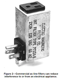
A: An external ac-line filter may reduce the noise. The filter plugs into an ac outlet, and the appliance plugs into the filter. The blender will still be noisy, but your location should be much quieter because the filter keeps the noise from being conducted onto the power-line, which can act as an antenna, radiating the noise. An ac-line filter can also help prevent ac noise from entering an appliance via the ac line. It may make a stereo, or station receiver, perform better if noise is being conducted on the ac line. Note that a surge filter is probably not an ac-line filter. Ac-line filters are often available at electrical supply houses and other retail outlets. Industrial Communications Engineers (ICE) is one manufacturer of commercial ac-line filters. [2] Figure 2 shows an ac line filter.
Figure 2—Commercial ac-line filters can reduce interference to or from an electrical appliance.

Q: That’s better! I hear no noise on 40 meters and higher frequencies, but 80 meters still has a moderately strong, steady buzzing that goes away on rainy days. Is that a bad power line? Should I contact the power company?
A: The noise is affected by weather, so it’s outdoors and probably something connected to the power lines. (If the noise only appeared at night, I would suspect a street lamp. Their starting circuits can become noisy as they cycle on and off trying to start a bad lamp. Many street lamps use gas-discharge bulbs, which can cause noise.) Although most high utility power distribution systems generate some noise, FCC regulations prohibit them from interfering with communications. If power-company equipment is the noise source, the utility company must correct it. (They are not responsible for interference caused by their customers, however.) In theory, you could report the problem to the utility company and expect them to correct it. In practice, however, the experience with each utility varies quite a bit. Even those with the necessary personnel and equipment to diagnose the problem may have a long waiting list for corrections. In most cases, it’s best for you to locate the problem for them. A combination of the techniques we’ve discussed can often identify a specific pole. First, track the problem to a neighborhood using the AM-broadcast band, then switch to VHF to get close. Once you are close, you may be able to hear or see the arc! A careful inspection with a set of binoculars may prove productive.

Q: I’ve narrowed the search to a city block. What can I do from here?
A: Call the utility repair people and leave the solution to them. In many cases, defective or cracked pole hardware causes electrical noise. Hardware and live lines occasionally fall from poles during repairs or when someone strikes a pole. Leave this danger to those trained to deal with it! The utility companies usually have sophisticated equipment and a trained RFI investigator who identifies the problem pole. With that done, the repair office dispatches a crew to make the repairs.

Q: Okay, I won’t touch the poles, but I’m curious. What kind of things can go wrong?
A: Cracked or dirty insulators can permit arcing from a line to the pole. Wire ties that secure lines to insulators can come loose, resulting in a strong arc. Ground wires can fail with an intermittent open, or with small arcs where the wire fastens to the pole. In most cases, the power companies recognize these problems and can correct them easily. Few people realize, however, that any loose hardware on a pole is suspect.
A: crew may check out a pole and declare that everything looks good except for a loose bolt holding two cross braces together. These braces do not connect to the line, so the crew does not consider them a problem. Nonetheless, the strong electric field near the high-voltage wires induces current into all nearby conductors. When those conductors are firmly bonded or separated by insulation, all is well. Otherwise, a small spark can develop between the conductors and radiate a lot of RF energy. If the service folks tighten that loose bolt, the noise might stop.

Q: I want to buy a house that is near high-voltage lines. Do you think I’ll have noise problems?
A: You might—or might not. Older lines are more prone to problems than newer lines. Age causes deterioration and newer hardware is designed with electrical noise in mind. Lines that the utility has upgraded from lower-voltage duty also have more problems, as a rule. It’s best to take your portable receiver to the site on a clear, dry day and give a listen. Talk to the neighbors, too. Ask about their TV reception. Slowly rolling, intermittent black lines appearing on all TVs indicate power-line noise.

Q: Is there more to learn?
A: Oh, yeah! We have only touched on electrical noise—source location, a few simple cures and working with the power company. My favorite book on the sub-ject is the Interference Handbook, by William Nelson, WA6FQG. Nelson is a retired RFI troubleshooter for Southern California Edison Company with many years of experience. ARRL’s Radio Frequency Interference How to Find It and Fix It covers a wide range of interference topics. Whole chapters explain power-line interference and how to work effectively with your neighbors. I also recommend Transmitter Hunting: Radio Direction Finding Simplified. See the ARRL Publications Catalog elsewhere in this issue for information about ordering these publications.

Thanks to Harry Thomas, KA1NH, and Jody Boucher, WA1ZBL, for their contributions to this article.

Notes
1W. Leavitt, W3AZ, “A Line-Noise ‘Sniffer’ that Works,” QST, Sep 1992, pp 52-55.
2Industrial Communications Engineers, PO Box 18495, Indianapolis, IN 46218-0495; tel 317-545-5412.

June QST: Lab Notes - June 1996 - Page 1
ARRL 1996 QST/QEX/NCJ CD C i ht (C) 1997 b Th A i R di R l L I

Thursday, April 2, 2009

02/04/2009 - FAKTA MENARIK NIH!!!!

KO ORANG RENUNG2 KAN LAH..... TAK TAU LAH JIWA YG TERUSIK BOLEH TERUSIK KE TIDAK.... HE HE


slmt pagi murid2 semua
..hari ini kita bajar bab kentuutttttttttt


1. Dari mana asal kentut?
Dari gas dalam usus.
Gas dalam usus berasal dari udara yg kita telan, gas yang menerobos ke usus dari darah, gas dari reaksi kimia dan gas dari bakteria dalam perut.

2. Apa komposisi kentut?
Bervariasi. Makin banyak udara anda telan, makin banyak kadar nitrogen dalam kentut (oksigen dari udara diaserap oleh tubuh sebelum sampai di usus). Adanya bakteria serta reaksi kimia antara asam perut dan cairan usus menghasilkan karbon dioksida. Bakteria juga menghasilkan metana dan hidrogen. Propors masing-masing gas tergantung apa yang anda makan, berapa banyak udara tertelan, jenis bakteria dalam usus, berapa lama kita menahan kentut. Makin lama menahan kentut, makin besar proporsi nitrogen, kerana gas-gas
lain terserap oleh darah melalui dinding usus. Orang yang makannya tergesa-gesa kadar oksigen dalam kentut lebih banyak kerana tubuhnya tidak sempat menyerap oksigen.

3. Kenapa kentut berbau busuk?
Bau kentut kerana kandungan hidrogen sulfida & merkaptan. Kedua bahan ini mengandung sulfur (belerang). Makin banyak kandungan sulfur dalam makanan anda, makin banyak sulfida & merkaptan diproduksi oleh bakteri dalam perut & makin busuklah kentut anda. Telur & daging mempunyai peranan besar dalam memproduksi bau busuk kentut. Kacang-kacang berperanan dalam memproduksi volume kentut bukan dalam kebusukannya.

4. Kenapa kentut menimbulkan bunyi?
Kerana adanya vibrasi lubang `anus` saat kentut diproduksi. Kerasnya bunyi bergantung pada kecepatan gas.

5. Kenapa kentut yg busuk itu hangat & tidak berbunyi?
Salah satu sumber kentut adalah bakteria. Fermentasi bakteria & proses pencernaan memproduksi panas, hasil sampingannya adalah gas busuk. Ukuran gelembung gas lebih kecil dan hangat dengan produk metabolisme bakteria yg berbau busuk. Ini kemudiannya menjadi kentut, walau hanya kecil volumenya,tapi SBD (Silent But Deadly)

6. Berapa banyak kentut diproduksi sehari?
Rata-rata setengah liter sehari dalam 14 kali kentut.

7. Mengapa kentut keluar melalui lubang dubur?
Kerana density-nya lebih ringan, kenapa gas kentut tidak melakukan perjalanan ke atas? Tidak demikian. Gerak peristaltik usus mendorong isinya ke arah bawah. Tekanan di sekitar `anus` lebih rendah. Gerak peristaltik usus menjadikan ruang mempunyai tekanan, sehingga memaksa isi usus, termasuk gas-nya untuk bergerak ke kawasan yang bertekanan lebih rendah, iaitu sekitar `anus`. Dalam perjalanan ke arah `anus` gelembung-gelembung kecil bergabung jadi gelembung besar. Kalau tidak ada gerak peristaltik, gelembung
gasakan menerobos ke atas lagi, tapi tidak terlalu jauh, kerana bentuk usus yg rumit & berbelit-belit.

8. Berapa waktu yang diperlukan oleh kentut untuk melakukan perjalanan ke hidung orang lain?
Bergantung kepada kondisi udara, seperti kelembaban, suhu, kecepatan & arah angin, berat molekul gas kentut, jarak antara 'transmitter' dengan 'receiver'. Begitu meninggalkan sumbernya, gas kentut menyebar & konsentrasinya berkurang. Kalau kentut tidak dikesan dalam beberapa detik, bererti ianya mengalami pengcernaan di udara & hilang ditelan udara selama-lamanya. Kecuali kalau anda kentut di ruang sempit, seperti lift, kereta, konsentrasinya lebih banyak, sehingga baunya akan berlegar dalam waktu yang agak lama
sampai akhirnya diserap dinding.

9. Apakah setiap orang kentut?
Sudah pasti, kalau masih hidup. Sesaat setelah meninggalpun orang masih boleh kentut.

10. Betulkah lelaki kentut lebih kerap daripada perempuan?
Tidak ada kaitannya dengan gender... Kalau benar, bererti perempu an menahan kentutnya, & apabla mahu kentut, banyak sekali jumlah yg dikeluarkan.

11. Saat apa biasanya orang kentut?
Pagi hari di toilet. yang disebut "morning thunder". Kalau resonansinya bagus, boleh didengar di seluruh penjuru rumah.

12. Mengapa makan kekacang menyebabkan banyak kentut?
Kekacang mengandung zat gula yg tidak boleh dicerna tubuh. Gula tersebut (raffinose, stachiose, verbascose) jika sampai di usus, bakteria di usus berpesta & membuat banyak gas. Jagung, kubis, susu juga penyebab banyak kentut (bukan baunya!).

13. Selain makanan, apa lagi penyebab kentut?
Udara yang tertelan, makan terburu-buru, makan tanpa dikunyah, minum `soft drink`, naik pesawat udara (kerana tekanan udara lebih rendah, sehingga gas di dalam usus mengalami ekspansi & muncul sebagai kentut).

14. Apakah kentut sama dengan sendawa, tapi muncul dari lain lubang?
Tidak... sendawa muncul dari perut, komposisi kimianya lain dengan kentut. Sendawa mengandung udara lebih banyak, kentut mengandung gas yang diproduksi oleh bakteria lebih banyak.

15. Kemana perginya gas kentut kalau ditahan tidak dikeluarkan?
Bukan..tetapi diserap oleh darah, bukan hilang kerana bocor..Tapi bermigrasi ke bahagian atas menuju usus & pada gilirannya akan keluar juga. Jadi bukan lenyap, tapi hanya mengalami penundaan.

16. Mungkinkah kentut terbakar?
Boleh saja. Kentut mengandung metana, hidrogen yg combustible (gas alam mengandung komponen ini juga). Kalau terbakar, nyala-nya berwarna biru kerana kandungan unsur hidrogen.

17. Bolehkah menyalakan mancis dengan kentut?
Jangan mengada-ada...
konsistensinya lain. Juga suhunya tidak cukup panas untuk memulakan pembakaran.

18. Mengapa kentut anjing & kucing lebih busuk?
Kerana anjing & kucing adalah karnivor (pemakan daging). Daging kaya dengan protein. Protein mengandung banyak sulfur, jadi bau kentut binatang ini lebih busuk. Lain dengan herbivor seperti kambing, kuda, gajah, yang memproduksi kentut lebih banyak, lebih lama, lebih kuat bunyinya, tapi relatif tidak berbau.

19. Betulkah pening kepala kalau mencium bau kentut 2-3 kali berturut-turut?
Kentut mengandung sedikit oksigen, mungkin sedikit saja anda mengalami pening kepala kalau mencium bau kentut terlalu banyak.

20. Apakah warna kentut?
Tidak berwarna.

21. Apakah kentut itu asid atau neutral?
Asid, kerana mengandung karbondioksisa (CO2) & hidrogen sulfida (H2S).

22. Apa yang terjadi kalau seseorang kentut di planet Venus?
Planet Venus sudah banyak mengandungi sulfur (belerang) di lapisan udaranya, jadi kentut di sana tidak ada kesannya.

Byknye perkataan KENTUT....

Friday, January 9, 2009

Pertandingan Bowling Ujang POWER Bowl

Title: Pertandingan Bowling Ujang POWER Bowl
Date: 14/2/2009 . Closing on 6/2/2009
Categories: Single , Team of 4
Fees: Single RM100, Team RM400

Contact me if u want the entry form, i'll fax or email to you

[IMG]http://i24.photobucket.com/albums/c28/relaksaja/pixposterbowling.jpg[/IMG]

Monday, December 22, 2008

22/12/2008 - Cigarette Name story

Cigarette Name story

I am
Peter Stuyvesant
I have two friends,
Benson and Hedges
I came from the city of
Marlboro,
In the
Salem high country
I Always carry a
Mild Seven
I rode on a
White Horse
Going to Kingsway in
Kent
It was
Lucky Strike I fell in love
With the daughter of
Master Duke
Her name Was
YSL
We got married by
Perillys , the priest
We checked in at the house of
Dunhill
And booked into room number
555
I laid her on the bed made of
Gold Leaf
I played with her two
Matterhorns
When I poked in my
Rothmans King Size
She cried in delight, 'You are a
Rough Rider !!!'
You are riding like a mad
Camel
When I asked her if she is satisfied
She answered' I want
MORE! !!!'
Then suddenly she turned around and asked me if I want to enter her
Gudang Garam.
She said... depan belakang puas, barulah
SAMPOERNA!!!

Monday, August 11, 2008

11/8/2008 - lama dah tak update...

sibuk sesangat. ari ni pun sbb ada seseorang yang mambuat aku teringat ttg blog ni..so, masuk ler sekejap...

last one month, sibuk terkejar kehulu-kehilir...
mula-mula event keusahawan di Temerlo, pastu di Jalan Kapar, Klang...
pastu o.station kat C.Highland.. gi ulang balik Sg. Besar bbrp kali.. aduss...
dgn hal2 minat radio amatur juga leh tahan, byk eyeball, repair repeter la.. dsb
2 minggu lepas balik kpg, orang tua suruh..buah2 tgh meranym.. tu pun kena buat kerja jugak jumpa customer sana...last week gi melaka pulak, 2 hari.. smlm naik puncak lg...
mmg letih... tp kehidupan begitu mmg menyeronokkan..

Friday, May 2, 2008

SLIM JIM ANTENNA for 2mtr @ 146.00MHz

part:
used old tv antenna,
my wife broomstick

tools:
ribet, drill, measuring tape, insulator tape.
SWR tested using Diamond SX27P : ICOM V8 - okey, but not checked with SWR meter
ICOM 2200H: Low (5w) - ard 1.2 , power 5w Mid Low (10w) - between 1.2 - 1.5, power 9-11 Mid (25w) - between 1.2 - 1.5, power 24-26 High (65w) - ard 1.5, power can't read needle full.

detail to refer to pix album...